photographs
refurbishment
description
refurbishment
Emulator
Museum Exhibits
| Radar Head photographs |
Console 61 refurbishment |
Console 64 description |
Console 64 refurbishment |
Radar Emulator |
Photographs of Museum Exhibits |
This article appeared in the September 2001 edition of the CHIDE magazine "Transmission Lines".
Please see also the Air Publication for this Display System.
The origins of RPDS may probably be traced back to the first use of radar photography, for operational purposes, at the CHL station at Walton-on the-Naze in February/March 1940. At that time, enemy aircraft, under cover of darkness, were causing problems by laying mines in the approaches to the Thames Estuary. An experimental Baird camera, with integral processor and forming part of the Company's development of television displays, was used to photograph the amplitude modulated trace (together with time and bearing information). The film could be immediately processed and be ready for collection by the Admiralty the following morning for assistance in mine-sweeping operations.
By 1943, TRE was evaluating the 'Skiatron' or colour trace tube. The Skiatron consisted of a normal cathode ray tube but with a halide (normally potassium iodide) screen in place of the more normal phosphor. The screen of the Skiatron stained purple when struck by the electron beam and the resulting 'afterglow' was controlled by the amount of light and heat applied to the screen. Amongst other applications, the Skiatron appeared to provide the potential for development of a large screen radar display for use in GCI stations. An experimental model, providing a picture some 5 feet in diameter, on a vertical screen, was built and underwent trials at the TRE experimental GCI station at Sledge Green. For mainly technical reasons, the trials were not a success but operational interest in large screen displays remained. Other Skiatron displays were developed, both direct viewing and by projection. One of the latter was the Console Type 10, giving a horizontal, back-projected picture some 30 inches in diameter, and developed jointly with the Admiralty.
Discussions on large screen displays had been taking place with G Wikkenhauser of Henry Hughes and Son (the scientific instrument manufacturers), who had previously been working with Scophony Television. He loaned an experimental rapid film processing device to TRE which was, to say the least, crude and unreliable. However, with it came various suggestions for improvements. One of these suggestions was to use pressure jets to apply the chemicals to the film emulsion. Following many discussions, a development contract was placed with Henry Hughes (later to become Kelvin and Hughes) for such a jet processing system with potential for cathode ray tube (crt) photography and projection of the film or to a large screen.
 |
Development models of the radar photographic display system were tested and evaluated at TRE as early as 1948 and, in September 1950, the Air Ministry placed a requirement on the Works Department, at the request of the C-in-C, Fighter Command, for a well (later known as 'the udder') measuring 12ft x 20ft x 15ft, in underground ROTOR buildings, centrally positioned in the operations room, to accommodate the RPDS. However, orders for RPDS equipments did not receive Air Council approval until 1953 and were ordered as part of the ROTOR 2 programme. In 1951, a prototype model of the radar photographic display system had been included in a demonstration of data handling and display equipments to the Air Ministry and Fighter Command. This demonstration also included an early prototype of the fixed-coil Type 64 display and a demonstration 10cm radar which would be developed into the radar Type 80.
This model, providing a general situations map from the digital track stores, processed each successive frame in 15 seconds and provided a relatively high contrast projected picture some six feet in diameter.
From this point development continued to overcome various problems, including leakage of chemicals, fogging of film, and uniform definition and registration in the projected picture. Finally, the equipment received production approval resulting in the RPDS type 1498. The first production models were installed in 'H' Block, the TRE building constructed as a replica of the planned Main Control Centre (MCC) at Bawburgh. Two systems were installed for evaluation, one as an enlarged radar display and the second as an MCC General Situation Display (GSD), the latter being driven by the digital track information storage system.
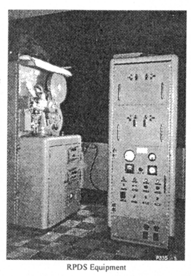
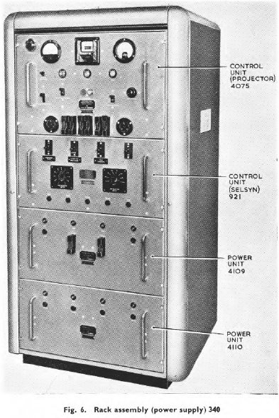
A single RPDS system consisted of four main components; a projector console; a power supply and control rack; and a mirror to deflect the projection beam on to a display screen. In order to allow continuous operation, an installation comprised dual projector consoles and supply racks with the mirror allowing the picture from either projector to be deflected on to the horizontal (or vertical) display screen. In the radar application, the photography of the 7" crt face took place in synchronism with the radar aerial scan, providing an exposure time of 10 or 15 seconds, corresponding to aerial rotation speeds of 4 or 6 rpm. This exposure time being regulated by the rotation of a camshaft driven in synchronism with the radar aerial through a selsyn repeater system. In the GSD application, photography would take place over one scan cycle of the digital stored information, which could be as low as 5 seconds but was normally of the order of 10 seconds.
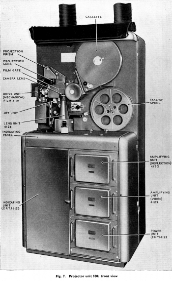
The following explanations relate primarily to the radar application but, apart from the method of information scanning, applies equally to the GSD application. The photography and projection mechanism consisted of three, in-line film positions; the camera aperture, the processing aperture and the projection aperture. The camera lens has a relative aperture of f/2 and a focal length of 2 inches.
The aperture is opened for one revolution of the radar aerial by a drum type shutter which closes for 1/50 revolution of the camshaft during film transport. The fact that no photography takes place while the camera shutter is closed makes little difference to the projected picture since the after-glow, from radar echoes occurring during the 'blind' sector, starts to record immediately the shutter opens and, though fading, continues to record on the film for the remaining 352.8° of aerial rotation until the shutter closes again. Also, a radar echo which occurs just before the transport, at the end of one rotation of the aerial, will be photographed later than one which occurs just before film transport.
Because of this, the positions of aircraft represented on the final picture are progressively more out-of-date, reading in a direction opposite to the rotation of the crt trace. Accurate interpretation of the picture is assisted if the film transport occurs at a known bearing and facilities for this are provided. On completion of photography, the film is transported during an interval (7.2°) when the camera shutter is closed, into the processing position where jets of developer, fixer, wash and drying air are delivered during the next exposure cycle. The action of the jets is controlled by means of an electrically operated four-way tap which supplies compressed air to each of the jets, sequentially, in the ratios 1: 1: 1: for the developer, fixer and wash operations and 1.4 for the drying operation. Finally, on the third cycle the film is transported into the projection position.
In the projector console the three processing solutions are contained in glass bottles inverted over constant level chambers. The outlets from the constant level chambers are connected to the liquid lines of the appropriate jets and the levels are such that the liquids in the connecting lines reach to within about 1/2 inch of the jets. After being sprayed on to the film, the exhausted liquids fall to the bottom of the processing pot from where they are drained off into a waste tank.
The film used is 35mm, safety base, negative panchromatic material with a grey anti-halation backing, enclosed in a light-tight cassette taking 2000ft of film, but more normally loaded with 1000ft. The spacing between adjacent apertures is equal to ten sprocket holes which, with 1000ft of film normally loaded, would last for 24 hours at an operating speed of four frames per minute. In order to avoid light creepage and fogging during film transport, due to internal reflections along the film, the film is crimped between each station.
In the projection aperture the film is blown against an optically flat glass plate which accurately locates it in the object plane of the projection lens. Since the film and the plate are in near optical contact, reflections from the surface of the glass and the back of the film tend to cause interference fringes which appear as coloured rings on the final picture. In order to reduce this effect the surfaces of the glass are heavily bloomed to minimise reflection.
The projection light source is a 1kW, two electrode mercury vapour lamp containing argon gas at a pressure of two atmospheres. The normal projection lens had a relative aperture f/2 (normally used at f/4 to obtain uniform definition over the projected area) with a focal length of 50mm. In the lamp house, light from the mercury arc passes horizontally through five condenser lenses and mounted behind the arc lamp is a concave mirror to obtain maximum efficiency from the light source.
Mounted between the second and third condenser lenses is a special glass which acts as a barrier to infra-red rays, thus reducing the amount of heat reaching the projection aperture. After entering the film gate the light is reflected through 90° by a plane mirror and passes vertically through two more condenser lenses. Between the final lens and the film is an aperture plate which determines the shape of the final picture, which is normally circular for radar purposes. After passing vertically through the film, the light is reflected horizontally by means of a mirror or prism.
The RPDS was first introduced into the Control and Reporting System under the ROTOR programme, being installed in various CEW and GCI stations. Different versions of the equipment existed but the differences lay mainly in the size and shape of the final projected picture and did not alter the general description given above. The exposed film could be stored and replayed, at any time, for training purposes. The replay of film had also been successfully used to plot the tracks of missing aircraft and so to determine likely search and rescue areas.
 |
 |
If you have any comments, complaints, suggestions, requests etc, please drop me a line via my Genuki email page.
Page last updated 30th January 2018 by Colin Hinson.