Balzers EHV 110A Electronics
Whilst working for a company that dealt with Balzers equipment, I drew many circuits of this in my own time so that I could better understand how it worked. I came from a Search Radar background and so had dealt with EHT (EHV) equipment before, but never using it to control High Vacuum coaters - quite a steep learning curve!
You are welcome to download and use these circuits for your own personal use, but not to upload them to another website - I drew these and they are my copyright.
Also below are photographs of the EHV110 giving Balzers part numbers.
Any feedback would be appreciated, and I will try to answer any questions relating to these systems.
Circuit (schematic) diagrams of the Balzers EHV system
- An overall diagram showing and explaining how the EHV system works.
- An overall diagram showing the emission control circuitry.
- A circuit diagram of the EHV rack
- A diagram showing the EHV rack cabling
- A circuit diagram of the EHV110A and the EKS110A showing both the internal circuitry and the interconnections.
- A circuit diagram showing the high voltage control sections, this includes the HV regulator board and the Cathode bias board.
- A circuit diagram showing the interlock circuitry of the EHV110 and EKS110.
- A circuit diagram showing the Power Distribution of the EHV rack.
- The individual circuit boards:
- The Emission Control board, and the same board with the relvant external circuitry.
- The Coil Current Control board, and, shown as a block but complete with external circuitry.
- The Water, and Crucible drive relay circuitry.
- The Relay board (unit E1)
- The ETS110 crucible control unit (this has several corrections to the original Balzers circuit)
- The Digital Wobble board.
- The Signal Print board.
- The SCR driver board.
- During my time working on the High Vacuum stuff, I designed and built a test rig built into an old EHV unit that would enable me to simulate the whole of the EHV rack working (apart from the actual EHV).
- This is the circuit for the whole of the test system - it includes a normal EHV110 and EKS110 unit so that they can be tested.
- I also built into this unit a relay tester (this is shown in the above circuit too).
- The wiring diagram for the external connections to the EHV110 in the test rig.
- The wiring diagram for the external connections to the EKS110 in the test rig.
- And finally, a circuit diagram of the RVG040 Vacuum Valve controller.
Photographs giving Balzers part numbers
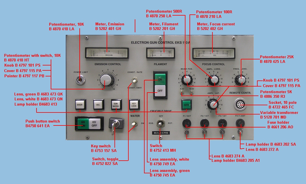
- EKS110A front panel
- EKS110A internal
- EKS110A internal PCBs
- EKS110A rear panel
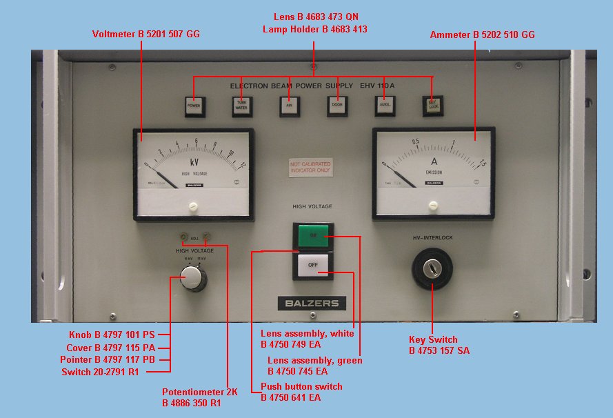
- EHV110A front panel
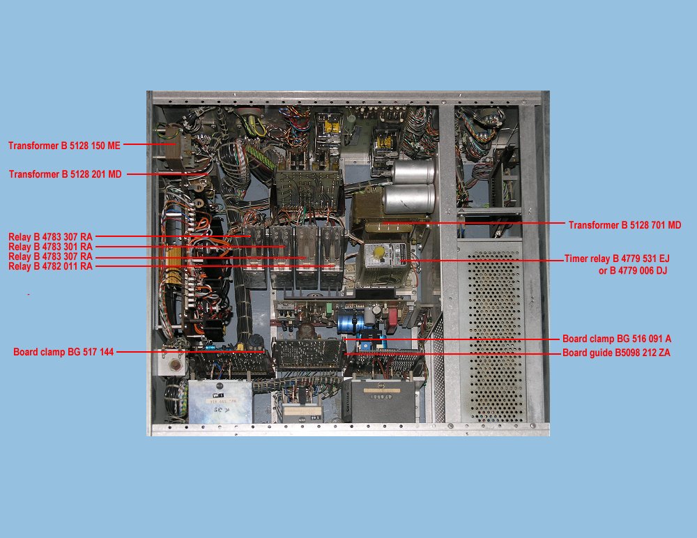
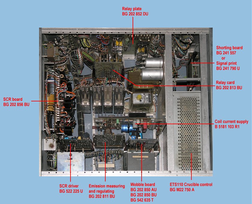
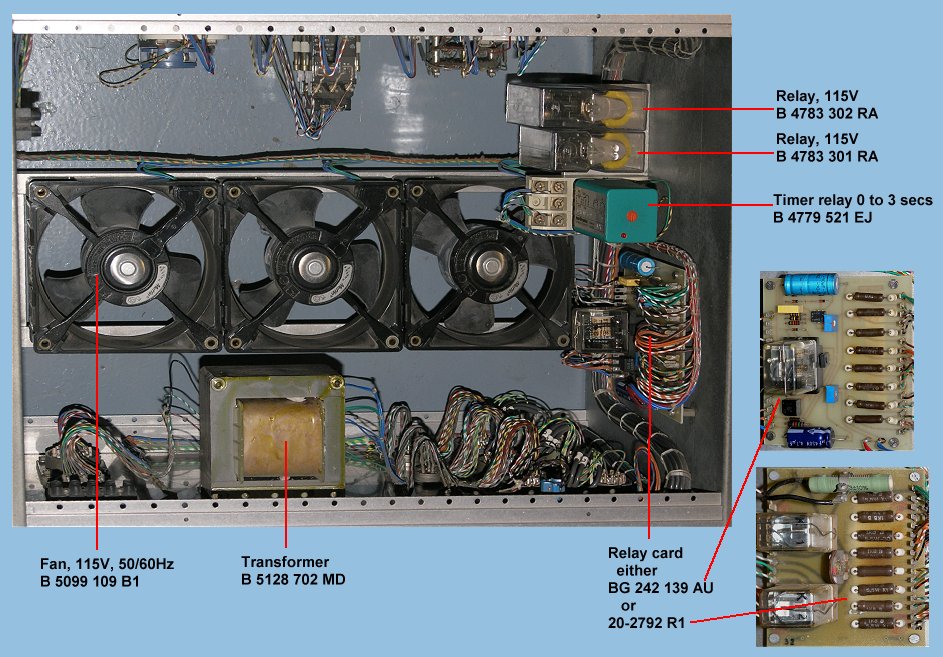
- EHV110A internal
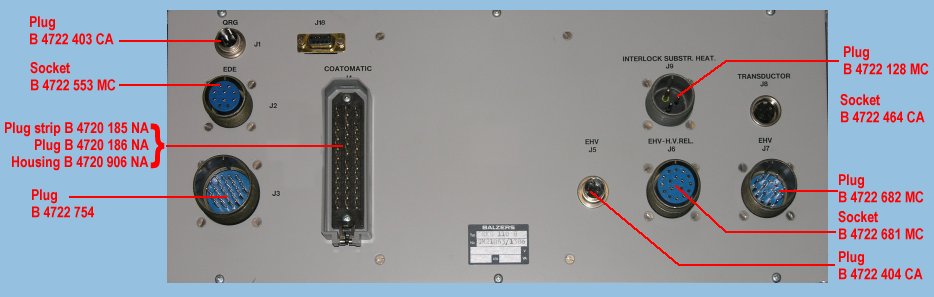
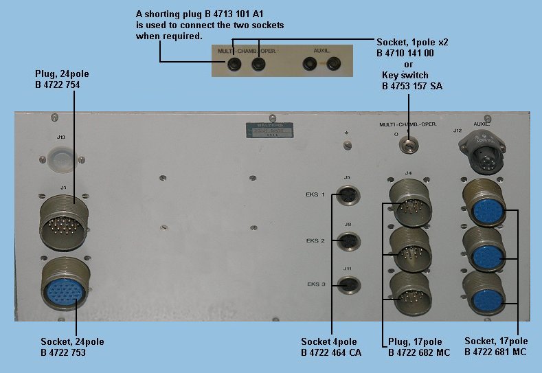
- EHV110A rear panel
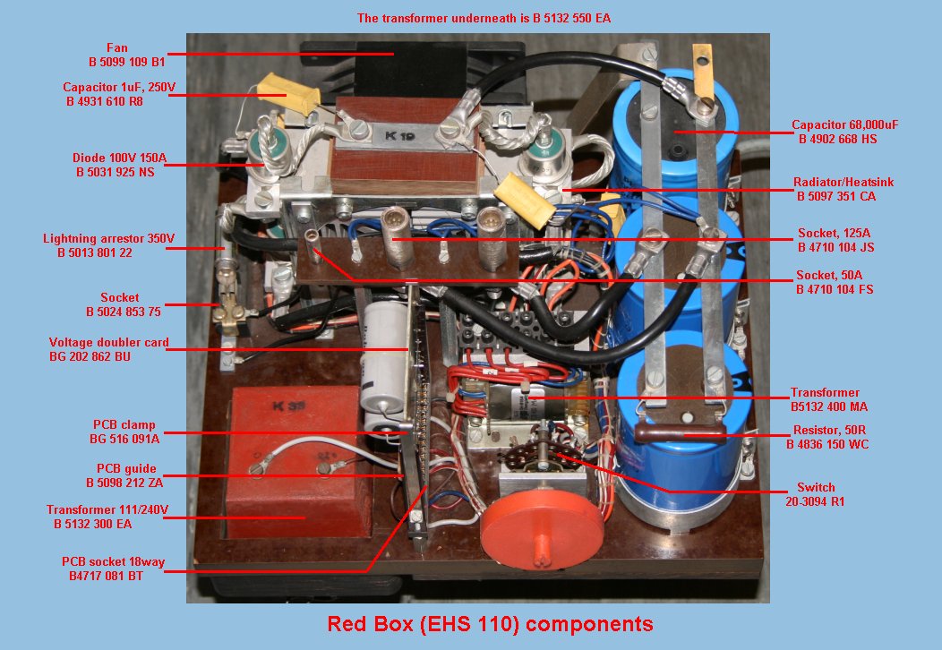
- EHS110 (Red box)
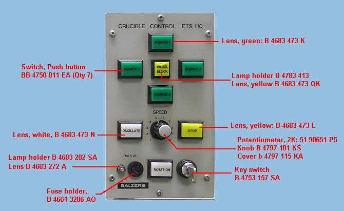
- ETS110 (Crucible control) front panel
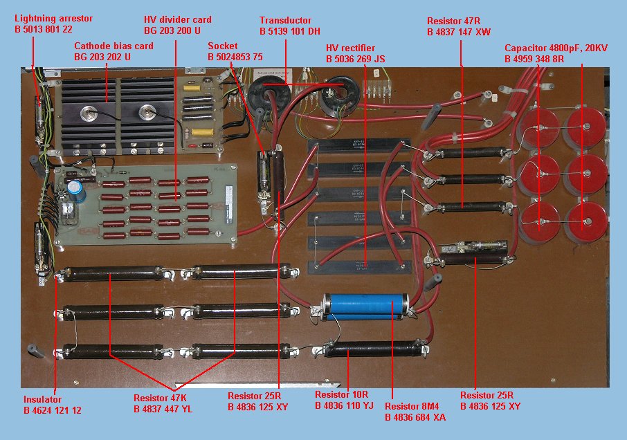
- High voltage board
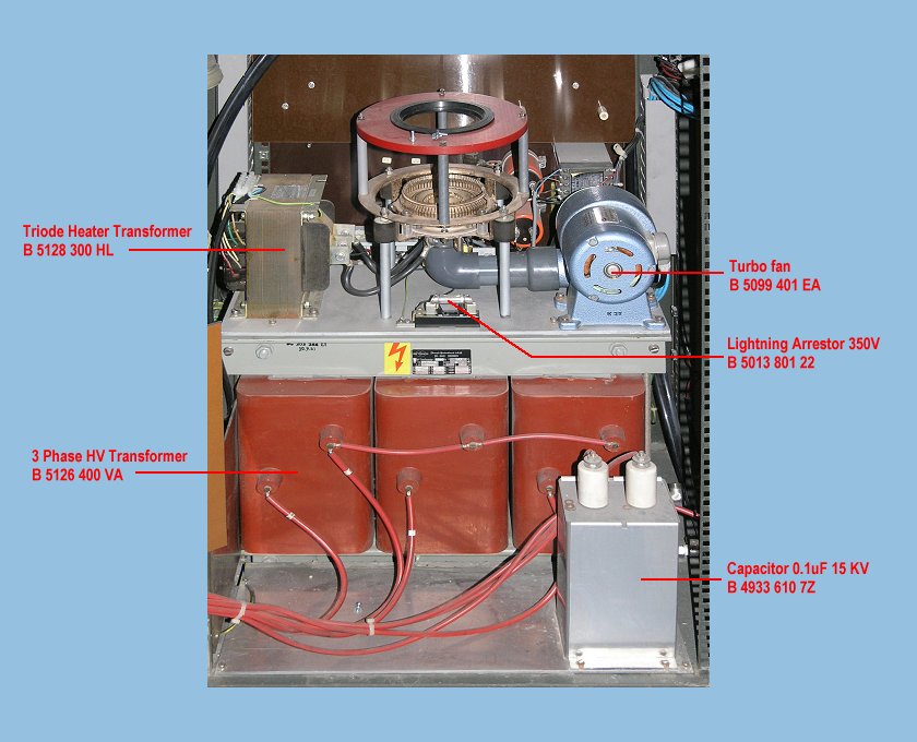
- EHV rack bottom
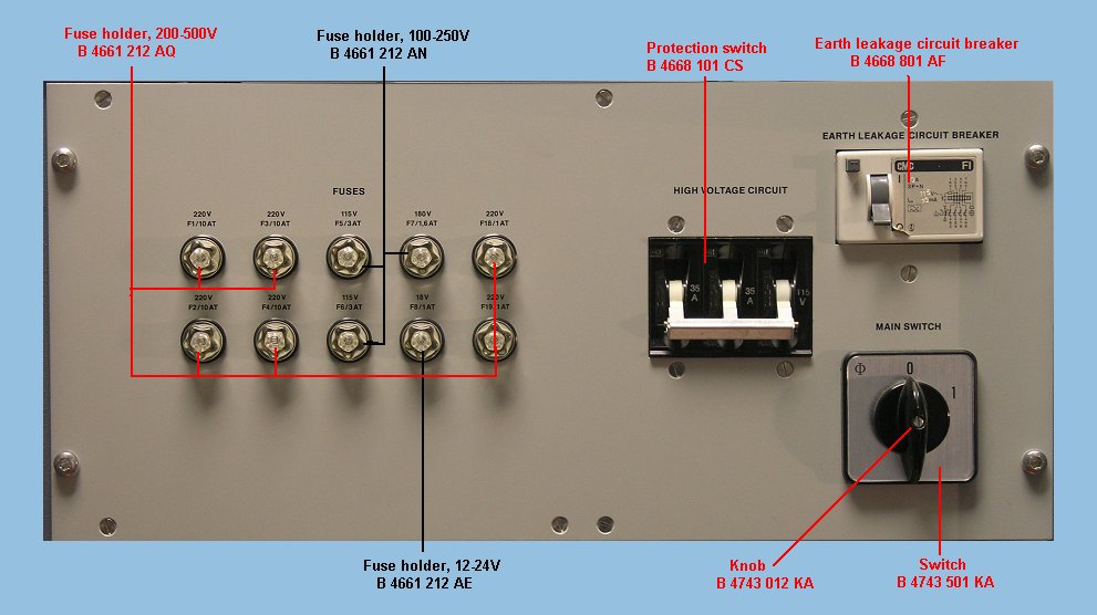
- EHV rack power supply control
If you have any comments, complaints, suggestions, requests etc, please drop me a line via my Genuki email page.
Page last updated 8th May 2024 by Colin Hinson.