photographs
refurbishment
description
refurbishment
Emulator
Museum Exhibits
| Radar Head photographs |
Console 61 refurbishment |
Console 64 description |
Console 64 refurbishment |
Radar Emulator |
Photographs of Museum Exhibits |
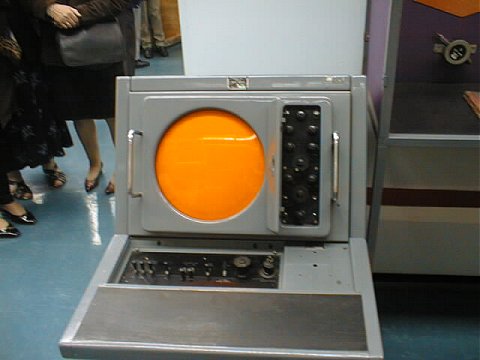
If you were trained at Locking on the Fixed Coil system, then the chances are that you worked on this very console!
The photo above was taken at RAF Locking in 1998.
The design for the Console 64 was started in 1949 by the Marconi company at Chelmsford. The aim was to complete the design and have prototypes by 1953 which they managed to do. I first met the Console 64 in my training as an apprentice at RAF Locking in 1958.
Wing Commander John Brown OBE (ex Marconi) wrote an article headed "A British successs, the Console 64" for "Transmission Lines" in 2000 and has kindly given permission for it to appear on this site. There is also an extract from an article about the development of the Console 64 by Roy Simons on the Marconi Radar History site, and you will find the R.A.F. Locking training notes for Fixed Coil here (as a pdf document).
The console was intended as a Plan Position Indicator (PPI) display originally, but was later used for height finder displays too (Fixed Coil phase 1a). As a PPI display it was capable of displaying radar signals, IFF signals, range rings, and video map, and, as I understand it, a strobe marker in the inter-trace period to show where the height finder was pointing and a range marker to show the range of the target (I never saw this in operation, though we do have this in operation at the museum).
Phase 1: as I understand it, in order to get the height of an aircraft, the PPI operator would gain control of the height finder and had a velocity control to control the azication of the height finder head, and a range control to control the range of a Range Strobe (this looked like a double range ring). There was then voice communication between the PPI operator and the height finder operator (on a Console 61) in order for the PPI operator to get the height of the relevant aircraft.
The range strobe marker was generated by feeding 300volts from the Console 61 to the Range control on the Console 64 and then feeding the output of the Range control back to the Console 61. Circuitry in the console 61 then generated a pair of pulses delayed from the input trigger by a time related to the voltage fed back from the Range control. This pulse is the Range Strobe and was fed to the Console 64 to give the range marker on the PPI display.
Phase 1A: these consoles had a joystick as part of the control desk. The joystick controlled an inter-trace dot (or circle etc.). Moving the joystick from one extreme to the other would give a movement of around 2 inches. There was a button on top of the joystick which when pressed would give the dot velocity in the direction that the joystick was pointing. This allowed the dot to be moved to anywhere on the screen. In order to get the height of an aircraft, the operator would set the dot on the aircraft return that he wanted the height of and then press the request switch. This would put the request in a queue and when a height finder became available, a strobe marker about half an inch long would appear on the screen under the control of the height finder head. This strobe would rotate round the screen until it layed on the relevant aircraft and (hopefully) the height finder operator would be able to see the aircraft return on their display - they would then move a "tadpole" marker to the centre of the aircraft return and press the height switch on the control desk. The voltage from the height finder joystick would then be sent to a height computer (electro-mechanical) which would calculate the height and send it to an indicator on the PPI desk. In fact there were 3 height indicators on the desk, one for the first height (usually the aircraft being intercepted), one for the second height (usually the fighter under control) and the third giving the height difference. Under Phase 1A, the Console 64 was also used for the height finder display.
The electrical units in the Console 64 were:
The Console 64 does not contain any power supplies (though it does have heater transformers on the input panel) - they were supplied by power supplies situated in the Radar Office in the BPS (Bulk power supply) and the "Negative Reference" rack, along with a 50v supply for the relays generated by a rotary DC generator. The idea behind having the power supplies remote was to reduce the amount of heat in "Fighter Cabins" which had 3 consoles in them though there was still an enormous amount of heat generated and removed by forced air. The supplies were as follows:
In order to generate a normal display, the Console 64 requires the above supplies plus:
Into the video amp via the Control panel:
Into the WFG 80:
Into the deflection amps:
The Radar bright up is fed into the WFG 80 and modified by the Anti-clutter switch (if on). The anti-clutter removes the first 20 miles of the Radar bright up to remove the ground returns. The resulting waveform is fed into the Video amp along with the trace compensation which allows adjustment of the brightness of the trace to equalise the brightness from the centre to the outer part of the trace.
Unless otherwise stated, all photographs © Colin Hinson, all rights reserved.
Page last updated 24th February 2018 by Colin Hinson.